Step 2: Control board
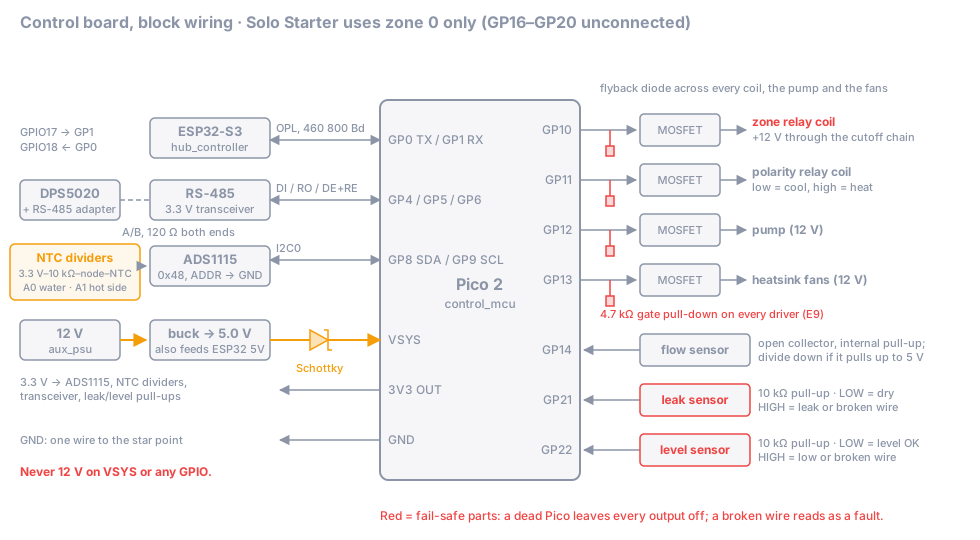
Goal: a Pico 2 on a perfboard that reads two temperatures, a flow sensor, a leak sensor and a level sensor, talks Modbus (RS-485) to the DPS5020 and OPL (UART) to the hub, and drives four outputs (zone relay, polarity relay, pump, fans) that are off whenever the Pico is not actively driving them.
Time: 5–7 h.
Parts
| Role / item | Qty | Notes |
|---|---|---|
control_mcu (Raspberry Pi Pico 2) |
1 | with header pins |
hub_controller (ESP32-S3-DevKitC-1) |
1 | wired in this step, flashed in step 6 |
temp_sensors: inline G1/4 10k NTC (water) + a 10k NTC for the heatsink base |
1 + 1 | |
leak_sensor |
1 | needs an output that is closed to GND only while powered and dry (see below) |
temp_sensors: ADS1115 breakout, 3.3 V |
1 | address 0x48 (ADDR pin to GND); the firmware reads only this one |
temp_sensors: 10 kΩ 0.1 % resistors |
2 | NTC divider top resistors |
| 3.3 V RS-485 transceiver (no role yet) | 1 | Pico side; with DE and /RE pins, or an auto-direction module (then GP6 stays unused) |
| TTL-to-RS-485 adapter (no role yet) | 1 | DPS5020 side (step 3) |
| Logic-level N-channel MOSFETs (fully on at V_GS = 3.3 V, ≥ 2 A) (no role yet) | 4 | zone relay, polarity relay(s), pump, fans; a 4-channel 3.3 V MOSFET module works too (add the pull-downs at its inputs, check for flyback diodes) |
| Flyback diodes (1N4007 / 1N5408 class) (no role yet) | 4 | one across each relay coil, pump and fan group |
| Gate resistors 220 Ω, pull-down resistors 4.7 kΩ (no role yet) | 4 + 4 | see the E9 note below |
| 10 kΩ pull-up resistors (no role yet) | 2 | leak and level inputs |
| 12 V → 5 V buck module, ≥ 1 A (no role yet) | 1 | powers Pico and ESP32 |
| Schottky diode (1N5819 class) (no role yet) | 1 | Pico VSYS back-feed protection |
| Perfboard, pin headers, screw terminals, 0.25–0.5 mm² wire |
The reservoir level sensor belongs to the reservoir role and the flow sensor to flow_sensor; you wire their
signal inputs here and mount them in step 5.
Pin map
From board.rs and WIRING.md. A Solo build
uses only the zone 0 pins; leave GP16–GP20 unconnected.
| Pico 2 pin | Function | Connects to |
|---|---|---|
| GP0 / GP1 | UART0 TX / RX, OPL 460 800 Bd | ESP32-S3 GPIO18 (RX) / GPIO17 (TX), crossed over |
| GP4 / GP5 | UART1 TX / RX, Modbus 9 600 Bd | RS-485 transceiver DI / RO |
| GP6 | RS-485 DE + /RE (high = transmit) | transceiver DE and /RE tied together |
| GP8 / GP9 | I2C0 SDA / SCL | ADS1115 SDA / SCL |
| GP10 | zone relay, zone 0 | MOSFET gate (relay coil goes through the cutoff chain) |
| GP11 | polarity relay, zone 0 (low = cool, high = heat) | MOSFET gate |
| GP12 | pump on, zone 0 | MOSFET gate |
| GP13 | fans on, zone 0 | MOSFET gate |
| GP14 | flow sensor pulses, zone 0 | sensor output (open collector; the firmware enables the internal pull-up) |
| GP21 | leak sensor: LOW = dry; HIGH = leak or broken wire | 10 kΩ pull-up to 3.3 V |
| GP22 | water level: LOW = OK; HIGH = low or broken wire | 10 kΩ pull-up to 3.3 V |
ADS1115 channels: A0 = water NTC (inline, return line), A1 = hot-side NTC (heatsink base). A2/A3 are zone 1 and stay unconnected.
Steps
2.1 Power and ground
- Mount the 12 V → 5 V buck module. Set its output to 5.0 V before you connect anything to it.
- Feed the Pico through the Schottky diode into VSYS (pin 39): buck 5 V → diode anode, diode cathode → VSYS. The diode stops the 5 V rail from back-feeding into your computer when USB is plugged in.
- Feed the ESP32-S3 from the same 5 V rail on its 5V pin. Don’t plug the ESP32’s USB in while the 5 V rail is on unless you have checked that your board protects against back-feed.
- Plan one star ground point near the DPS5020 (step 3): 24 V negative, 12 V negative and the control board GND meet there and only there. Run one solid GND wire from the board to the star point.
⚠️ Never put 12 V on VSYS or on any Pico pin. The Pico takes 1.8–5.5 V on VSYS; the GPIOs are 3.3 V.
2.2 ADS1115 and NTC dividers
- ADS1115: VDD → Pico 3V3 OUT (pin 36), GND → GND, SDA → GP8, SCL → GP9, ADDR → GND (address 0x48). Most breakouts already have I2C pull-ups to VDD; if yours doesn’t, add 4.7 kΩ from SDA and SCL to 3.3 V.
- For each NTC build a divider: 3.3 V → 10 kΩ 0.1 % → node → NTC → GND. The node goes to the ADS input (A0 water, A1 hot side). This orientation matters: the firmware computes R_NTC = 10 kΩ · V / (3.3 V − V).
- Use a two-wire screw terminal for each NTC so you can swap sensors.
2.3 RS-485 to the DPS5020
- Transceiver VCC → 3.3 V, GND → GND, DI → GP4, RO → GP5, DE and /RE tied together → GP6. (Auto-direction modules have no DE pin: TX → GP4, RX → GP5, GP6 unconnected; the firmware still toggles it, harmlessly.)
- Bring A and B out to a screw terminal. The bus goes to the TTL-to-RS-485 adapter at the DPS in step 3.
- Termination: 120 Ω between A and B at both ends of the bus (many adapter boards have a jumper or a fitted resistor; check, don’t double it).
2.4 Hub UART
ESP32-S3 GPIO17 (TX) → Pico GP1, GPIO18 (RX) ← Pico GP0, plus a GND wire alongside. Keep these wires short (≤ 20 cm); the link runs at 460 800 Bd.
2.5 Output drivers (fail-off)
Build four identical low-side switches, one each for GP10 (zone relay), GP11 (polarity relay), GP12 (pump), GP13 (fans):
- MOSFET source → GND. Drain → the negative side of the load. The load’s positive side goes to +12 V (for the zone relay: +12 V through the cutoff chain, see step 3).
- Gate ← GPIO through a 220 Ω resistor.
- Pull-down: gate → GND, 4.7 kΩ, mounted right at the MOSFET.
- Flyback diode across every inductive load (each relay coil, the pump, the fan group): cathode to the +12 V side.
⚠️ Why external pull-downs (RP2350 erratum E9): an RP2350 that is in reset, unflashed or crashed must leave every
driver off. The RP2350’s internal pull-downs can’t be relied on for this (erratum E9), and the erratum’s workaround
needs an external pull-down of 8.2 kΩ or less. The project uses 4.7 kΩ (WIRING.md, board.rs). The
checkpoint below verifies it on your board.
2.6 Fail-safe inputs: leak and level
Both inputs are wired so that a broken wire reads as a fault:
- 10 kΩ pull-up from GP21 to 3.3 V, and from GP22 to 3.3 V.
- The sensor must pull the pin to GND only in the good state (dry / level OK). Leak, low water, an unplugged
connector, a cut wire or an unpowered sensor all leave the pin HIGH, and the firmware raises
LEAK(latching) orLOW_WATER. - Leak modules with a relay output (
leak_sensorexamples): use the contact that is closed only while the module is powered and dry. On modules whose relay is energized in the healthy state that is the NO contact; check yours with a multimeter (dry → continuity; wet sensing cable → open; module unplugged → open). Wire one side of that contact to GP21, the other to GND. - Level sensor: if its output is HIGH when water is present, add an NPN inverter at the Pico end (sensor output → 10 kΩ → NPN base, emitter → GND, collector → GP22). A broken sensor wire then turns the NPN off and GP22 reads HIGH = fault, which keeps the fail-safe property. Some capacitive level sensors drive their supply voltage on the output (the one on the shopping list may): power it from 5 V, not 12 V, and measure the output in both states before you connect it. The inverter also keeps a 5 V output away from the GPIO.
⚠️ Never feed a 12 V signal into a GPIO. If a sensor module only offers a 12 V output, use a relay contact or an optocoupler.
2.7 Flow sensor input
- Flow sensor signal → GP14. The firmware turns on the internal pull-up, so an open-collector output works directly.
- Many hall flow sensors run on 5 V and pull their output up to 5 V internally. Power the sensor, leave GP14 disconnected, and measure the signal while you blow gently through it: if it goes above 3.3 V, add a divider (10 kΩ series, 20 kΩ to GND) in front of GP14.
✅ Checkpoint (Pico not yet flashed)
Do these with the 12 V brick on, the 24 V brick unplugged, and nothing connected to the relay/pump/fan outputs except what this step built.
- 5 V rail: 4.9–5.2 V. Pico 3V3 OUT: 3.25–3.35 V.
- Resistance gate → GND on each of the four MOSFETs (power off): ≈ 4.7 kΩ (slightly less with the Pico fitted).
- Pico held in reset (connect RUN, pin 30, to GND) and also with the Pico unflashed: every gate measures < 0.3 V, and nothing clicks or spins.
- Touch a gate briefly to 3.3 V through a 1 kΩ resistor: the polarity relay clicks; release: it drops. Repeat for pump and fan outputs (with pump/fans connected, the pump must have water in it or stay off < 1 s).
- NTC node voltages with the sensors at room temperature: ≈ 1.8 V at 20 °C, ≈ 1.65 V at 25 °C
(generic 10k NTC, β 3435). Unplugged sensor: ≈ 3.3 V. Shorted sensor: ≈ 0 V. The firmware rejects both
as
SENSOR_INVALID. - GP21 with the leak sensor dry and powered: < 0.3 V; leak sensor unplugged: ≈ 3.3 V; sensing cable touched with a wet paper towel: ≈ 3.3 V.
- GP22 with the level sensor seeing water: < 0.3 V; level sensor unplugged: ≈ 3.3 V.
NTC calibration
The inline sensors don’t publish their B-value (temp_sensors role). The water NTC drives the 45 °C trip, so
calibrate it:
- Ice bath (crushed ice + water, stirred): 0 °C. Measure the NTC resistance R₁ with the multimeter (sensor tip only in the water; keep the connector dry).
- Warm bath at ~40 °C, measured with your reference thermometer: T₂, R₂.
- Compute (T in kelvin):
- β = ln(R₁ / R₂) / (1/T₁ − 1/T₂)
- R₂₅ = R₁ · exp(β · (1/298.15 − 1/T₁))
- Compare with the firmware’s generic model (10 kΩ at 25 °C, β 3435): it predicts ≈ 28.7 kΩ at 0 °C and ≈ 5.76 kΩ at 40 °C.
If your sensor’s reading at 40 °C is more than 1 °C away from the generic model, you need a source build with
your values in NTC_CAL in board.rs (step 6). Prebuilt firmware always uses the generic values.
Write R₂₅ and β of both sensors into your build log either way.
If it fails
- Gate floats at 1–2 V with the Pico in reset: pull-down missing, wrong value or on the wrong side of the gate resistor. It must be gate → GND, at the MOSFET.
- Relay doesn’t click with 3.3 V on the gate: MOSFET not logic-level (check V_GS(th) and R_DS(on) at 3.3 V), or flyback diode reversed (that shorts the coil; it gets warm).
- NTC node at 3.3 V with the sensor plugged in: divider upside down, or open connector. At 0 V: NTC shorted, or divider upside down.
- Leak input never goes LOW: you picked the wrong relay contact, or the module needs power to close it. That is expected and correct: power it from the 12 V rail.
Rendered from docs/build/02-control-board.md. View or edit the source. Nobody has built this yet: if something is unclear or wrong, that is exactly what we need to know.