Step 4: Thermal stack
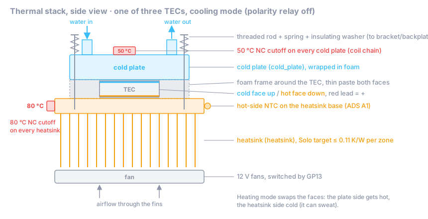
Goal: three TEC sandwiches (cold plate / TEC / heatsink) with even clamping pressure, the right TEC orientation, a 50 °C cutoff on every cold plate, an 80 °C cutoff on every heatsink, and the hot-side NTC on the heatsink base.
Time: 3–4 h.
Parts
| Role / item | Qty | Notes |
|---|---|---|
tec_module (40 × 40 mm, 127 couples, Imax ≈ 6 A) |
3 | from a seller with a datasheet |
cold_plate (40 × 40 mm aluminium water block, G1/4 or barbed) |
3 | all aluminium or all copper in the loop, never mixed |
heatsink (≤ 0.11 K/W per zone with fans on) |
1–3 | e.g. one CPU tower cooler per TEC; the real K/W is a measurement target |
| Heatsink fans, 12 V (120 mm class) (no role yet) | as needed | switched by GP13 |
thermal_cutoff 50 °C NC |
3 | one per cold plate |
thermal_cutoff 80 °C NC |
1 per heatsink | |
temp_sensors: 10k NTC for the heatsink base |
1 | the A1 channel |
| Non-conductive thermal paste (no role yet) | ||
| M3/M4 threaded rod, nuts, springs, insulating (nylon) washers, 3 mm aluminium backplate (no role yet) | 1 set per stack | the coolers’ CPU-socket mounts don’t fit a TEC; this replaces them |
| Closed-cell foam, ~4 mm (TEC thickness) (no role yet) | frame around each TEC, and insulation for the cold plates | |
| Kapton tape or a small clamp bracket for sensors (no role yet) |
Orientation: which side gets cold
In cooling mode the cold face of every TEC must touch its cold plate, and the hot face the heatsink. Coil off on the polarity relay = cool (step 3), and that puts red = + on all TECs.
On most TEC1-12706-class modules the printed side is the cold side with red on +, but sellers differ. Check every module:
- Put the TEC on the heatsink with a dab of paste, printed side up.
- From the DPS front panel, red = +, 1.0 A for at most 10 s.
- Touch the top face: if it gets cold, the top is the cold side. Mark it with a marker. If it gets warm, the bottom is the cold side; mark that.
⚠️ Never power a TEC without a heatsink, not even for a few seconds at full current. At 1 A on a heatsink for 10 s it is safe.
Steps
4.1 Test the cutoffs before mounting
Retail listings often mix up NO and NC (thermal_cutoff notes). For each cutoff:
- Multimeter on continuity across the two terminals at room temperature: closed (beep).
- Heat it with the hot-air gun next to your reference thermometer probe. It must open near its rating (50 °C or 80 °C, ± 5 °C tolerance) and close again as it cools.
- Write down the measured opening temperature of each unit. Reject parts that open more than 5 °C off.
4.2 Prepare the surfaces
- Clean the cold plate base, both TEC faces and the heatsink base with isopropyl alcohol. They must be flat and free of burrs.
- Cut a foam frame for each TEC: outer size as the cold plate, inner hole 40 × 40 mm. It reduces heat leaking back from the hot to the cold side around the TEC and keeps condensation off the TEC edges.
4.3 Assemble each sandwich
- Thin, even layer of non-conductive paste on the heatsink base where the TEC goes. Thin means you can almost see the metal through it.
- Place the TEC cold side up (your marking), leads pointing to where the wiring goes.
- Thin layer of paste on the TEC’s top face. Place the foam frame, then the cold plate, ports pointing the way the tubing will run.
- Clamp: four threaded rods hold the cold plate against the cooler base, anchored on the cooler’s mounting bracket or on a backplate (a tower cooler’s CPU-socket mount doesn’t fit a TEC; see the mounting line on the shopping list). Each rod gets a spring and an insulating washer on the cold-plate side, so the block and the cooler are not connected through metal. Tighten crosswise, a quarter turn at a time, until the springs are compressed by the same amount. Uneven pressure cracks TECs.
- Clamping force: follow your TEC’s datasheet. The project has no measured value yet; cold-plate thermal resistance with real clamping is open measurement item 2 in OPEN-DECISIONS.md. Write down what you did (screw size, spring, compression) so your measurement can be compared.
4.4 Mount the cutoffs and the hot-side NTC
- 50 °C cutoff on each cold plate: on the plate body (not on a tube), with a dab of paste, held by a bracket, screw
or a clamp. It must feel the water-side temperature of the TEC face, which is what it protects against
(
02-electrical-safety.md: the face runs above the water when heating). - 80 °C cutoff on each heatsink base: as close to the TEC as the fins allow, with paste and a bracket.
- Hot-side NTC (A1): on the heatsink base next to the TEC that will run hottest (the middle one if they share a heatsink; with one cooler per TEC, pick the one with the shortest fan airflow path and note which). Paste and kapton tape, or a drop of thermal epoxy. This is the sensor for the 75 °C firmware trip.
- Wire the cutoffs into the chain from step 3, with crimped or soldered and heat-shrunk joints. The chain carries only the relay coil current.
Note: the firmware reads one water NTC and one hot-side NTC per zone, so only one heatsink is watched in software; extra sensors per cold plate are planned (
temp_sensorsrole). The bimetal cutoffs on every plate and heatsink are your per-TEC protection. Don’t skip any of them.
4.5 TEC wiring
Connect all three red leads to the TEC + busbar and all three black leads to the TEC − busbar (parallel). Strain-relieve the thin TEC leads so the sandwich doesn’t pull on them.
4.6 Fans and insulation
- Mount the fans so they blow through the fins; connect them to the GP13 driver (on/off for now; PWM is future work in the firmware). With three tower coolers that is up to six fans on one output: check that the driver and the 12 V budget cope. 4-pin PWM fans with the PWM pin left open run at full speed, which is loud; fine for the bench, a problem for the bedroom (target ≤ 30 dB(A) at 1 m).
- Wrap each cold plate and its fittings in closed-cell foam, leaving the cutoffs’ leads accessible. Below the room
dew point, anything uninsulated will sweat (
02-electrical-safety.md, Condensation).
✅ Checkpoint
- Every cutoff opened within ± 5 °C of its rating in the hot-air test (values in the build log).
- Each TEC’s cold side is marked and faces its cold plate.
- Cutoff chain end to end at room temperature: < 1 Ω; heat any one cold-plate cutoff with the hot-air gun: chain opens.
- Resistance across the TEC busbars (DPS disconnected, measured quickly because the TECs generate a small voltage when warmed): ≈ 0.6–0.7 Ω for three 12706-class modules in parallel (datasheet ≈ 1.98 Ω each).
- Hot-side NTC node voltage at room temperature: ≈ 1.6–1.9 V (see step 2).
- Springs evenly compressed, no TEC visibly tilted, no paste squeezed onto the TEC leads.
If it fails
- Busbar resistance much higher than 0.7 Ω: a TEC lead not making contact. Much lower (≈ 0 Ω): a short at the terminal block.
- A TEC is cold on both sides / warm on both sides in the orientation test: damaged module or no heatsink contact.
Replace it; quality varies a lot between sellers (
tec_modulenotes). - Cutoff opens at 40 °C or not at all: wrong part (NO instead of NC, or wrong rating). Don’t use it.
Rendered from docs/build/04-thermal-stack.md. View or edit the source. Nobody has built this yet: if something is unclear or wrong, that is exactly what we need to know.